- Determination of the dynamic force acting on the component during placement under regular process conditions
- objective and independent measurement and analysis certified according to DIN ISO 9001
- Determination of causes for inaccurate placement forces and derivation of corrective measures
- Checking the effectiveness of corrections
- Calculation of \(C_m\) and \(C_{mk}\) values based on given specification limits
- Statement of conformity to the given specifications taking into account the measurement uncertainty and the given target values.
- Detailed and meaningful test report
- more information about the measuring method

Measurement Service for Determining Positioning Accuracy on SMT Equipment
Determination of Placement Force on Placement Equipment
Preparation from CeTaQ
- CAD data for creating the processing program, taking into account the characteristics of the plant to be investigated, such as..:
- Typical component shape
- Number of placement tools (heads, nozzles ...)
- mobile force gauge for carrying out the measurements
Preparation from Customer
- Executable machining program according to the specifications of the CAD data provided
- Ensuring a good condition of the system to be inspected by prior maintenance and, if necessary, calibration.
- Maintain a sufficient number of nozzles. Nozzles should be in good condition.
- Maintain a sufficient number of feeders. The feeders should be in a condition that allows faultless picking of the components. If picking errors occur, the measurement must be restarted.
- Table and power supply in the neighbourhood of the equipment to be tested for the construction of the measuring system.
- Technical support for setting up and operating the system
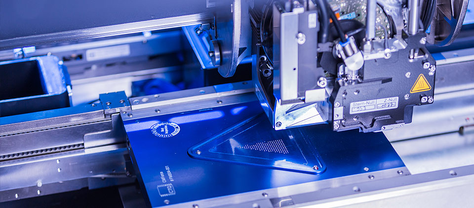
Assembly and Measurement
The plant to be examined is prepared by the technical support, the appropriate program is loaded and the components are prepared. The sensor board is then transported into the system and equipped according to the specifications. It is connected to a laptop. The laptop records the force curves during assembly. After completion of the assembly, these are analyzed.
Analysis of the Results
The force curves of each individual placement are extracted from the signal recorded during placement and assigned to the corresponding placement head. The maximum force and the duration are determined. Optionally, the force increases and the height of the first placement pulse can also be calculated. These allow conclusions to be drawn about the energy input into the component and are particularly helpful in determining the causes of broken components.
Use the Results for Optimization
In many cases, it is possible to derive corrective action to optimise accuracy immediately after analysis of the results. After the corrections have been carried out, their effectiveness is checked with a further measurement. Depending on the result, this may result in further measures followed by verification measurements.
Report Writing
On the basis of the final condition achieved, a test report is drawn up after completion of the work. This is usually done after the customer has visited our office. In addition to a detailed description of the final condition, the report contains all steps taken to achieve this condition.
- Measuring system is calibrated on the basis of international standards.
- The method is suitable for all pick-and-place systems whose transport system can accommodate the force gauge.
- The time required for a complete examination is usually between 10 minutes and 2 hours, depending on the type of system. Typical is 30 minutes.